Ryobi Charger DC Conversion
Failure
If I haven't documented it yet as this is being read hopefully soon I will be documenting my small solar power project. Preferably not here in the failure folder! Anyway, I have installed an array of solar panels on a ledge outside of my home office (computer, ham station, 3d printer room). This is an ~12V system with a 12V battery. Now the question is what to power with it. I thought moving my collection of various chargers to this room and connecting those would be a good start and thus this project.
My lovely wife buys me Ryobi tools for birthdays and Christmas. So now I have a large collection. Often she gets deals which includes a charger so at this point I have many. They are all 120V AC models. Typically I keep two chargers plugged in as I usually run down two batteries each weekend when cutting the lawn, one to run the trimmer and one to run the blower.
I do have an inverter that I can use. It is many years old and was kind of cheap even then. Or I could buy a new inverter. But I thought it would be more efficient not to convert to to AC and to try to run the chargers off DC.
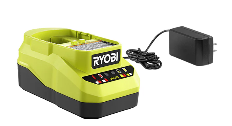
My favorite two chargers that I normally use are older universal models that charges both NiCAD and Lithium-ion batteries. The power supplies are internal and they plug directly into the wall. I don't think these would be easy for me to convert to DC. However, I also have two newer chargers that have wall-warts. The wall-warts are not detachable but I thought I could cut the wire and connect them to a DC supply. That should be easy right?
RyobiChargerDCConversion/PCG002.png
https://www.ryobitools.com/products/33287205264
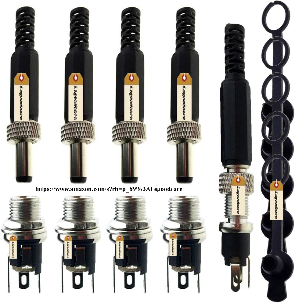
Of course I can never let it be that simple. I should have at least tried that with one and attempted to charge a battery that way before doing anything fancy. But that's just not me. Instead I I bought a pack of matching barrel plugs and sockets from Amazon. The chargers cases each had a little square hole that gripped the strain relief of the power wire. This was located on a round raised area that was just begging me to drill it out and install a round barrel socket.
RyobiChargerDCConversion/barrel_connectors.png
https://www.amazon.com/dp/B07LDZGXRQ
I opened the cases, cut the power wires flush with the inside of the strain reliefs, put it back together and drilled out the holes. Then I opened them up again, soldered the sockets to the remaining bits of wire, mounted them in the new holes and closed them back up. I also mounted the plugs on the now separated wall-warts so that I could still plug them in if I wanted to.
Looking at the labels on the wall-warts they said 18VDC. Oddly the label said nothing about current. Usually they list a set voltage and a maximum current. When I plugged on in and checked it with a volt meter I got all sorts of readings. Sometimes it was low, sometimes it was high. I thought maybe I wasn't getting good contact. Finally, it seemed like about 21.5V was the highest and most common measurement. Well, that is above the 18V on the sticker but hey, wallwarts are usually not very well regulated. I thought maybe it drops to 18V with the expected load but goes higher when ran unloaded with just a meter.
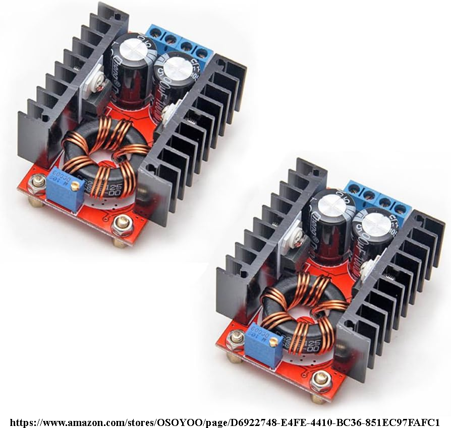
My solar setup only outputs 12V so I was going to need to step that up. Fortunately I had a couple DC-DC step up modules lying around which I had also purchased from Amazon for a different project that I did not end up using. So I added barrel jacks to a couple of scrap wires and wired one of the modules to my solar controller. The module was adjustable with a little set-screw pot so I adjusted it for 18V just like the sticker said.
RyobiChargerDCConversion/GoWoopsDC-DC-StepUp.png
https://www.amazon.com/dp/B00J1X4XXM
At this time I did not have a discharged battery, they were all full. So I plugged in one of the chargers and inserted a full battery. The red on the charger flashed several times, it paused then flashed again. This pattern continued indefinitely. I was not familiar with the lighting scheme on this pair of chargers but that did not sound good. So I unhooked the charger and plugged in one of the wall-warts. Again it flashed a few times and paused but after the pause it switched to a solid green light. Solid green seemed to indicate full if I was reading the pictogram on the charger right.
At this point I thought maybe the 18V on the label was for the battery it charges, not the actual output voltage. That half volt didn't seem right to me so I thought I would go for an even number and turned the voltage up to 22V. I reconnected the charger and plugged in my battery. The red light blinked, it paused then went solid green. Success! ...I thought.
The real test came Friday. I cut my lawn as normal and at the end had a couple of half-run down batteries. Great! So I connected up both chargers and plugged them in. The lights came on and looked good, blinking green for charging. But I checked the amps being drawn from the solar controller. 20 Amps! This was on the 12V side so there were 240 Watts at least going into the step up converter! I checked the heatsinks. They were getting hot. Even the power wire going into the module was hot! This was not ok. So I disconnected the power.
Ok, it clearly didn't work when I had it set to 18V. Maybe I was on the right track but 22V was too high? So I switched to 19V. At this point I figured the sticker on the wallwart was just telling me it went to 18V battery chargers and the real output specs were not listed. 19V is kind of a popular wallwart voltage or at least it was on laptops before USB-C. I plugged it in. The lights looked good. The current reading jumped around for a moment but not to anything particularly high and it settled on about 4.5 amps. Ok, this looks good I thought.
These batteries have 4-bar indicator LEDs on them. With these chargers the indicators come on as the batteries charge and indicate where it is at. So I was able to watch and the batteries made it up to 2 out of 4. Then they seemed to stop rising. I checked the current draw and it was down to around 0.2 or 0.3 amps. It had stalled. I even let them sit overnight. Nothing changed. So next I turned the voltage up to 20V. The amps being drawn jumped up to around 5. The batteries charged up to 3 out of 4 bars. Then they stalled again.
I could have turned them up again but I no longer believe this is an issue of picking the correct one voltage. Thinking back to when I had the chargers open I remember seeing lots of small surface-mount digital ICs. But I do not remember seeing any larger inductors or capacitors. I'm not sure why they need so many digital ICs just to run a few LED indicators but now I am thinking that the voltage selection and conversion is actually all happening in the wallwart. I don't think these wallwarts are just dumb semi-regulated power supplies with fixed voltages. I think their voltages track the battery state.
So, I think I am done. I don't think this "seemingly easy" conversion is so easy afterall but rather would require re-engineering the chargers entirely. I may go back and briefly try connecting a run-down battery at the current 20V setting. If I am right the current will shoot up, not as high as at 22V but still higher than what it was at 3 bars, probably too high. I may also open one of the chargers again and double check there are no big inductors. Or I can at least take a picture for this document. But I think this project is done. I will just have to buy a couple of chargers that are intended to run off 12VDC in the first place. I wish Ryobi made a 2-battery charger that runs off DC!
Better luck on your own projects!
Update
I just found someone else's project. They are trying to adapt the same charger to connect directly to a solar panel. That is not quite what I have in mind as I intend to connect to a charge controller and also connect other devices to the same supply. Also, running off of 12V I can always unhook it and take it to my car when needed. But.. I have started watching his videos and this looks promising.